Engineering/Lug Plate
Lug Plate Calculations
EN 14917 Annex K.8
1
Material Allowables
Material Input
Material Results
No material result yet.
2
Force Definition
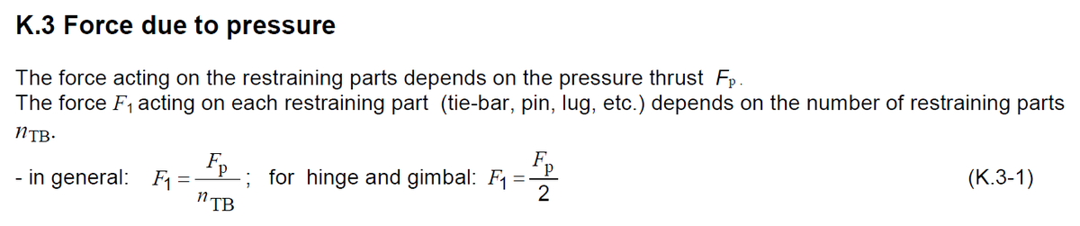
K.3 / K.5 Force Definition
Define pressure thrust and restraining force. Hinge/Gimbal uses angular movement. TB uses friction force Fy.
Force Results
No force result yet.
3
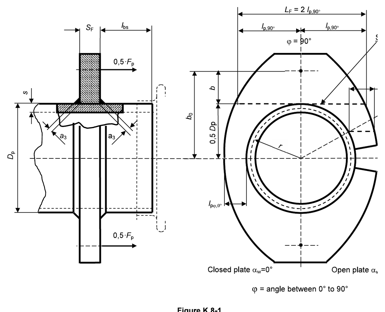
Stress in Sections Around the Pipe — K.8.1.1.1
Figure K.8-1
Inputs include SF, Dp, b/b0, αw, φ and lpφ.
Around Pipe Results
No around-pipe result yet.
4
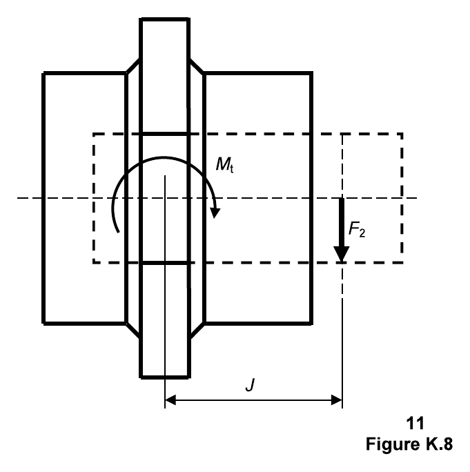
Stress in Section 1 — K.8.1.1.2
Figure K.8-2 — Hinge/Gimbal
Hinge/Gimbal uses F2 and J. Tie-bars uses Fy and lR.
Section 1 Results
No section 1 result yet.
5
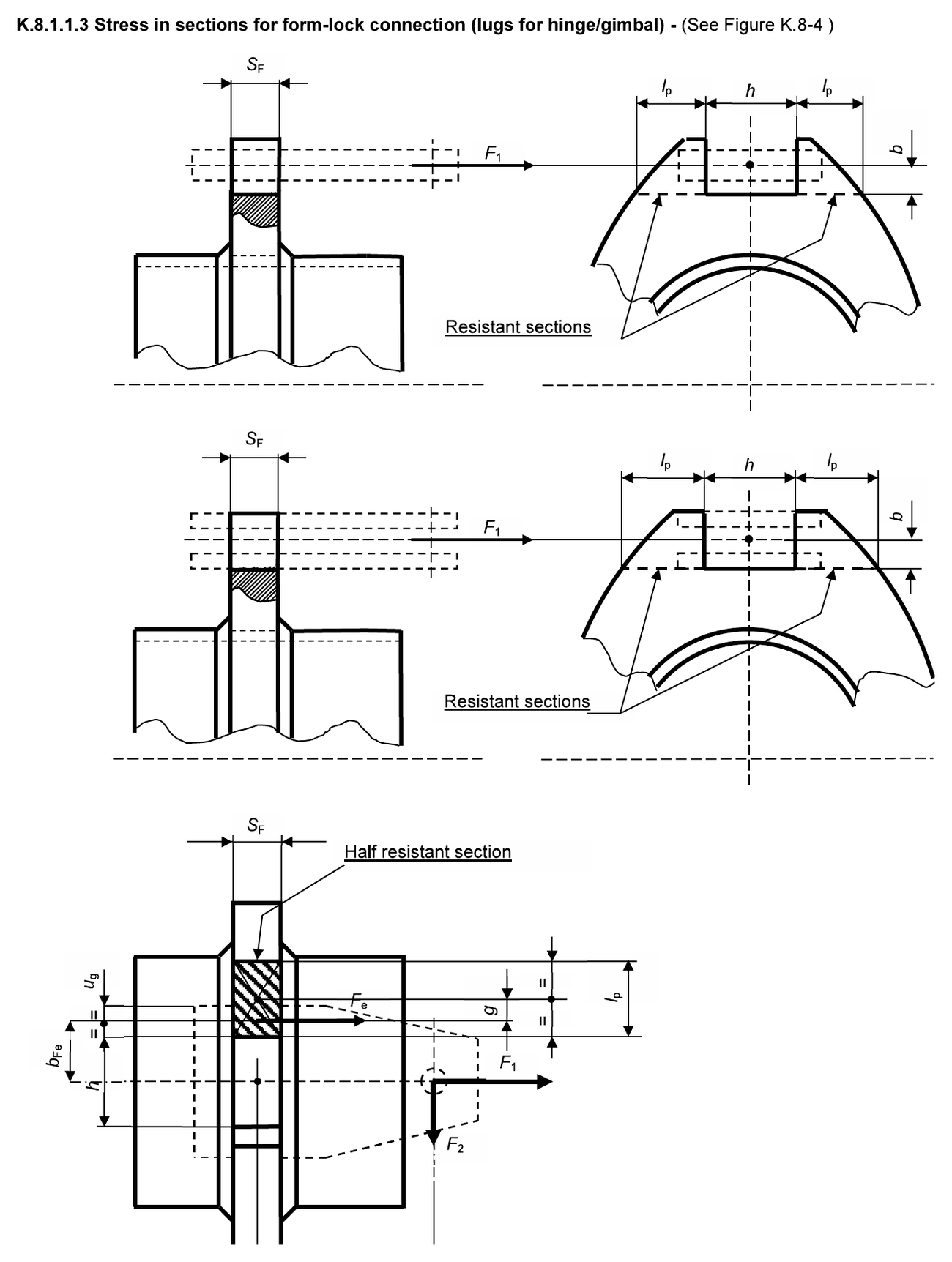
Stress in Sections for Form-lock Connection — K.8.1.1.3
Figure K.8-4 — Form-lock Connection
Inputs include lp, h and ug. This figure is different from welded buttonhole.
Form-lock Results
No form-lock result yet.
6
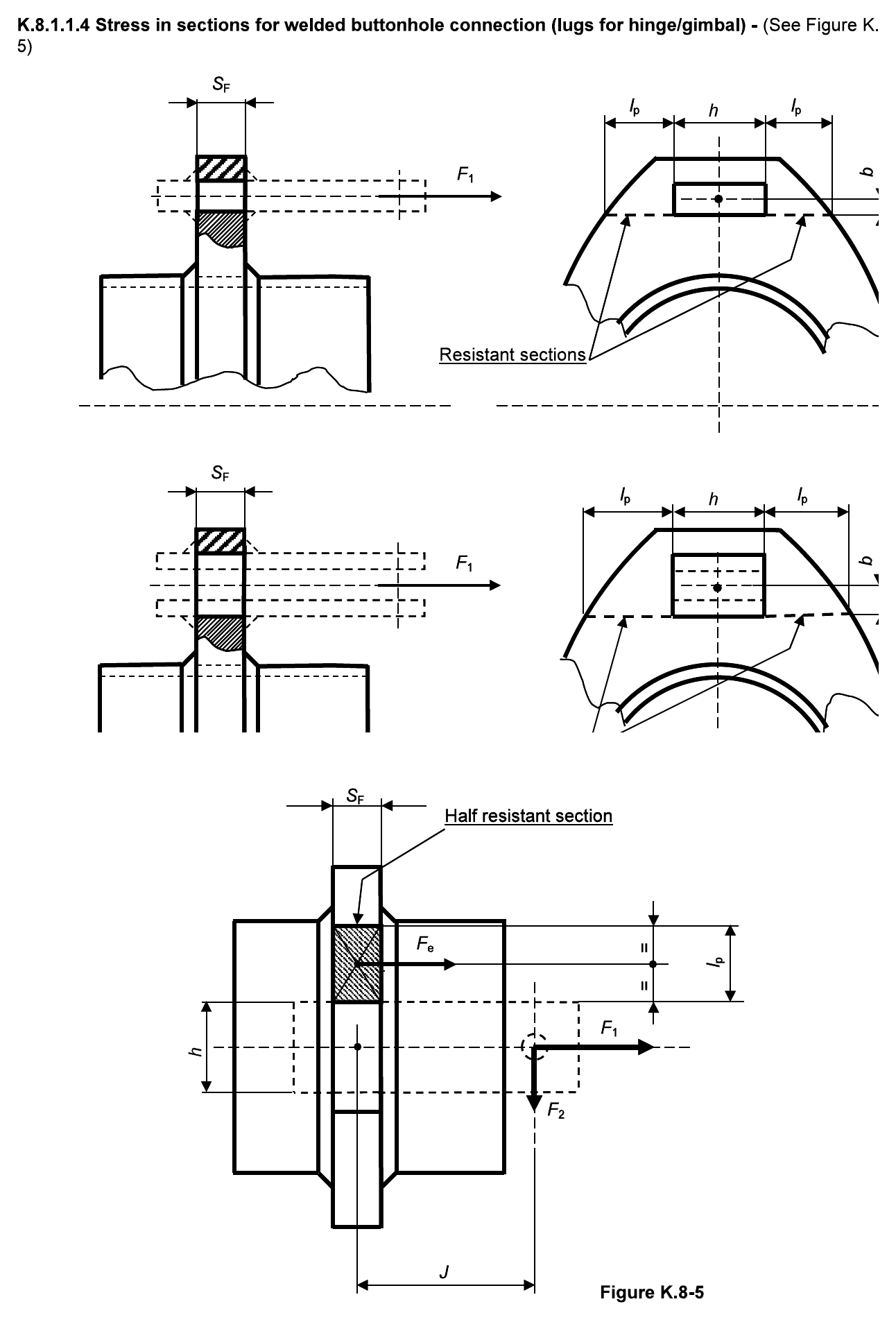
Stress in Sections for Welded Buttonhole Connection — K.8.1.1.4
Figure K.8-5 — Welded Buttonhole Connection
Different figure and inputs from form-lock. No ug input here.
Welded Buttonhole Results
No welded buttonhole result yet.
7
Stress in the Pipe — K.8.1.2
Figure K.8-1
Uses q1 and q2 from the Around Pipe calculation.
Pipe Stress Results
No pipe stress result yet.
8
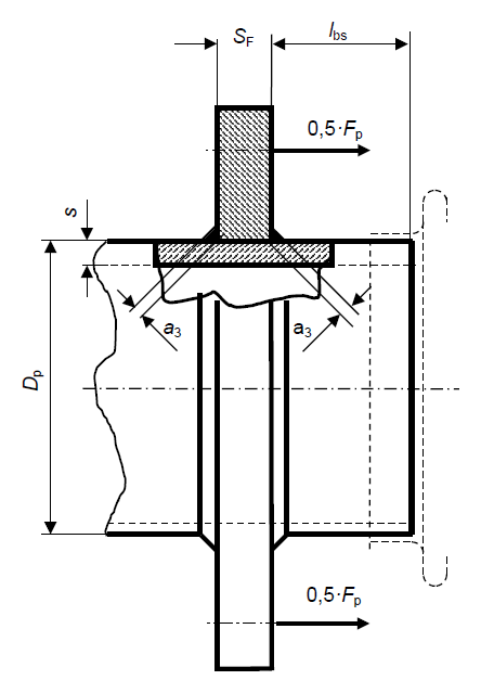
Stress in the Weld Plate/Pipe — K.8.1.3
a3 Weld Detail Figure
Use the weld detail image showing a3 throat thickness around pipe/plate weld.
Weld Stress Results
No weld stress result yet.